admin@pro-en.ir

admin@pro-en.ir

Intruduction

 A Brief History of Drawing 

1.1

For almost twenty thousand years a drawing has been the main way that ideas have been communicated. The first drawings were made even longer ago, when prehistoric man tried to communicate ideas by marking in the dirt floors of caves. It is natural for humans to graphically draw their ideas because drawing is a universal language. Even today, when some drawings are made by computers, this is true. The first permanent drawings, made on the rock walls of caves, depicted people, deer, buffalo, and other animals. These drawings were made to express emotion and record experiences, long before the development of writing. When writing developed, drawing came to be used primarily by artists and engineers as a means of showing design concepts for pyramids, war chariots, buildings, and simple mechanisms.
One of the earliest drawings, found in Mesopotamia, shows the use of the wheel about 3200 B.C. The drawing depicts a wheelbarrow-like mechanism being used by a man to transport his wife. This early drawing was a crude picture, without depth or perspective. Another example of early drawing is a floor plan of a fortress made on a clay tablet around 4000 B.C.
At the beginning of the Christian era, Roman architects had become skilled in making drawings of proposed buildings. They used straight edges and compasses to prepare plan (top), elevation (front and side), and perspective views.

 However, the theory behind engineering drawing, the theory that enabled architects to depict views on various planes, was not developed until the Renaissance period. Even though Leonardo da Vinci was probably aware of these theories, his classical training as an artist influenced his engineering drawings like the one shown in Fig. 1.1. No multiview drawings (top, front, side views) made by Leonardo have been found. He knew the value of pictorial drawing in showing how parts of a mechanism fit together. It is interesting to note that even in this day of space travel, engineers continue to use pictorials to supplement multiview drawings (see the pictorial drawing of Skylab in Fig. 1.2).
Most of the very early drawings still existing today were made on parchment, a very durable type of paper. Although the paper that was developed in Europe in the twelfth century made the use of drawings more prevalent, the paper was too fragile. Of the thousands of engineering drawings of fortresses, buildings, and mechanisms made during the twelfth through fifteenth centuries, only a few exist today. Pictures made into pottery, carvings, and weavings were more permanent than paper drawings, and many of these artifacts have survived.


FIG 1.1 IDEA sketch prepared byleonardo davinci(1452_1519) leonardo's automobile was to have been powered by two giant springs andsteered by the tiller, at the left in the picture, attached to the small wheel.( from collection of fine arts department, IBM corporation)

The Interrelationship of Engineering Drawing and Design 

1.2

Engineering design uses engineering drawing as the way to communicate and document ideas. Engineers, drafters, and other members of the design team must work closely on the design project and speak the same language: the language of engineering drawing. A design engineer, though not responsible for the actual production of the drawings, must be able to read and understand all aspects of the drawing. At the very least, the design engineer must be able to make clear, concise sketches that can be given to technologists and drafting technicians for the actual preparation of the drawings.
Any person on the design team who makes engineering drawings must combine classroom study of engineering graphics with practical experience in company methods, standards, and practices. This knowledge may include such things as manufacturing methods, numerical control, and digital computer applications (Chapters 1-5 and 12–18).
Engineering drawings present technical information to tens or even hundreds of individuals who may be engineers, managers, suppliers, machinists, installers, or repairmen.

 All need engineering drawings to complete their tasks. For this reason drawings must conform to exacting standards for their preparation and understanding.
Engineering drawings are documents that change. Over the life of a drawing, there may be changes in the design, materials, suppliers, and uses of the product. These changes must be noted and recorded. Very often a single drawing may be used for a whole family of parts. Consequently, engineering drawings must be made with materials and equipment that allow for clean and efficient changes.


FIG 1.2 skylab_manned orbital scientificspace station. the skylab wwas design to expand our knowledge of manned earth_orbital operations and toaccomplish carefullyselected scientific, technological,and medical investigations.(courtesy national Aeronotics and space administration)

 Engineering Drawing Today 

1.3


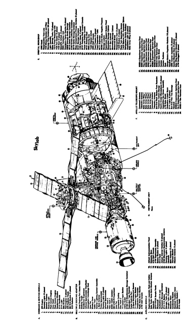
The design team is often made up of individuals from many different disciplines. A project manager assembles a team to accomplish a goal such as building a bridge, designing a car, or placing scientific equipment on the moon (Fig. 1.3). In general, the design team is comprised of three groups of individuals, each having particular knowledge of engineering drawing:    

(1) engineering designers,

(2) engineering technologists, and

(3) engineering technicians.

Designers and technologists think about the way that a mechanism or product works and how it can be manufactured or built. These individuals must have a working knowledge of engineering drawing to be able to direct drafters in the preparation of final drawings. The final drawings follow preliminary design sketches that the designer may have made. Such design sketches must follow the basic rules of engineering drawing so that it will be easy for the drafter to turn rough sketches into final drawings.

To be effective, the engineering designer and technologist must have skill in three areas of communication:

 (1) English, both written and oral; (2) symbols, as used in science and mathematics; and (3) engineering drawing, both sketching and interpreting drawings.
A drafter must be able to assemble written, numeric, and drawing information and make final drawings. These drawings are called “working drawings” because they are the drawings from which the product is made. The drawing must convey shape, size, and manufacturing information needed to fabricate the parts and assemble the structure. This must be done with knowledge of company practices and national and international standards such as those of the American National Standards Institute (ANSI) or the International Standards Organization (ISO). Since ANSI standards govern the preparation of engineering drawings, drafters must keep up to date with the latest published standards.
Engineering technicians, assigned to aid the engineer or to work in production, must have considerable knowledge in preparing engineering drawings. Those working with the design engineer may be called upon to solve problems graphically or prepare working sketches within their own areas of expertise, such as electrical, structural, or mechanical systems.
for correctness, since it is much easier to check a picture than 50 pages of numbers.
These computer-assisted drawings take on two general forms: (1) a chart (graph, plot, or diagram); or (2) a picture showing the shape or size of the object.With either form, the designer is trying to determine whether or not the computer model satisfies the design criteria. To do this, the designer must be able to read the drawing and understand shape, size, and manufacturing information as it is represented.

FIG 1.3. The lunar rover. The photograph shows the lunar rover takento the Moon by the apollo 15 mission .it is parked near mounted hadley in the right center back ground . The lunar rover isone of man's mostnoted innovative designs.(courtesey national Aeronautics and space Administration)

Drawing instruments

MANUAL DRAWING EQUIPMENT AND ITS USE

2.1 Introduction The instruments and materials needed for making engineering drawings are shown in Fig. 2.1. There will be individual differences among brands, but functionally the equipment will be the same. Drawing instruments should be well made. Inferior equipment often makes it difficult to produce drawings of professional quality and often costs more in the long run.

FIG 2.1 Manual drafting Equipment
FIG 2.2 A drawing instrument set


2.2 List of Equipment
and Materials The following list contains the selection of equipment necessary for making instrument drawings.

1. Case of drawing instruments

2. Drawing surface (board or table)
3. Drafting edge (T-square, parallel edge, drafting machine)
4. Triangles (30, 45 degree or adjustable) 

5. French curve 

6. Scales (see 2.24 and 2.25)
7. Drawing pencils 

8. Lead pointer 

9. Drafting tape 

10. Eraser 

11. Dry cleaning pad 

12. Erasing shield 

13. Dusting brush 

14. Drawing paper 

15. Tracing paper or drafting film

2.3 The Set of Drawing Instruments 

The minimum contents of a drawing instrument set should include a large bow compass, small bow compass, and set of frictional dividers (Fig. 2.2). Sets which contain the large bow are preferred by many persons, especially in the aircraft and automotive fields. The set often comes in a velvet-lined case, designed to protect the instruments. Some sets also contain a beam compass” for constructing large arcs. The bow compass has a center wheel for adjustment and will hold its setting as the draftsman applies
pressure to draw a line. Modern bow compasses often have a “quick bow” feature which allows rapid adjustment.


FIG 2.3 protractor
FIG 2.4 special templates

2.4 Protractor

The protractor (Fig. 2.3) is used for measuring and laying off angles. An alternative to this device is the protractor head of a drafting machine (Fig. 2.9).

2.4 Protractor The protractor (Fig. 2.3) is used for measuring and laying off angles. An alternative to this device is the protractor head of a drafting machine (Fig. 2.9).

FIG 2.5 flexible curves

2.5 Special Instruments and Templates

A few of the many special instruments available are shown in Figs. 2.4-2.8. Drafting templates are by far the most important special equipment. The use of templates (Fig. 2.4) can save valuable time in the drawing of standard figures and symbols. Electrical, hydraulic, and pneumatic equipment, springs, fasteners, gears, circles, ellipses, curves, boxes, and architectural symbols are all available on templates. Template manufacturers will make custom templates for specialized applications on request.
To supplement standard plastic curves, flexible curves (Fig. 2.5) provide limitless variations and are very convenient.


FIG 2.6 Erasing machine
FID 2.7 Technical fountation pen.(courtesey Koh_l_Noor,inc)


 The type shown in (a) is a lead bar enclosed in rubber. The more desirable one shown in (b) has a steel ruling edge attached to a spring with a lead core. Flexible curves are limited to gentle curves and are unsuitable for small radius arcs.
The electric erasing machine (Fig. 2.6) saves valuable drafting time for those persons who correct and update engineering drawings. An assortment of eraser stock is available for different papers and films.
When an ink drawing is required, the technical pen shown in Fig. 2.7 is available in the 13 metric line widths shown. These pens are suitable for instrument linework and for lettering using plastic lettering guides. For proper use, these pens should be held perpendicular to the drawing
papers and films. These pens require occasional cleaning. These are precision drawing instruments and users are advised to follow the manufacturer’s recommendations for filling, cleaning, and storing.
Proportional dividers (Fig. 2.8) supplement the dividers found in drawing instrument sets. They are used for reducing or enlarging drawings without converting numerical values.

FIG 2.8 Proportional Dividers


2.6 The T-Square, Parallel Edge and Drafting Machine 

The T-Square and Parallel Edge are used to draw horizontal lines and as a guide for triangles when drawing vertical and inclined lines (Figs. 2.25 and 2.26). Lines are drawn along the top of the straight edge.
The drafting machine (Fig. 2.9) combines straight edge, protractor, scale, and triangles. It is estimated that drafting machines lead to a 25-50% savings in time in commercial drafting rooms. Drafting machines may be of the parallel arm type or the more modern track” design. Some include a digital electronic readout of protractor angles, much like a calculator. Many optional devices may be attached to the head of a drafting machine including electronic lettering machines and computer-interfaced digitizers (see Sec. 2.32).

FIG 2.9 Drafting machine.Blades are in position for Drawing inclined Lines


2.7 Tracing Paper and Drafting Film 

White lightweight tracing paper called drafting vellum, on which pencil drawings can be made and from which prints can be produced, is used in most commercial drafting rooms. Drafting vellum is not a permanent medium for drawings, however. Over time it will swell with humidity, crack with dryness, or yellow with age. It also does not keep its dimensional stability,” that is, exacting distances will change over time as vellum shrinks. Drawings done on vellum must be reduced and stored on microfilm for permanence.

A more expensive solution is polyester drafting film. This film is transluscent (frosted on one or both sides) and exhibits excellent dimensional stability and printing qualities. Drawings are made on drafting film either in ink or polymer (plastic) lead. Erasures can be made without leaving ghost marks” that might show when making a print.

.


2.9Drawing Pencil Lines

Pencil lines should be sharp and uniform along their entire length as well as uniform with similar lines elsewhere on the drawing. Construction lines (preliminary or layout lines) should be drawn very lightly so that they will not reproduce when copied. Finished lines should be made boldly and distinctly so that a distinction will be evident between solid and dashed object lines and auxiliary lines (dimension, center, and section lines). To give this contrast, necessary for clearness and ease in reading the drawing, object lines should be of medium width and very black; dashed lines, black and less wide; and auxiliary lines, dark and thin.
When drawing a line, a .3, .5, or .7 millimeter mechanical pencil should be held perpendicular to the drawing surface (Fig. 2.12). This type of pencil will produce a line consistent with the diameter of the lead. Traditional wooden drawing pencils or lead holders like those in Fig. 2.13 should be inclined slightly (about 60 degrees) in the direction that the line is being drawn. The pencil should be “pulled” (never pushed) at the same inclination for the full length of the line. If the pencil is rotated slowly between the fingers as the line is drawn, a symmetrical point will be maintained and a straight uniform line will be ensured.


drafting pencil
FIG.2.10 drafting pencil
FIG 2.11 sharping a wood encased-pencil

2.8Pencils

Both the student and the professional should be equipped with a selection of pencils with leads of various degrees of hardness (Fig. 2.10). Examples of these leads are

FOR FILM

6P Hard Plastic

2P Medium Plastic

P Soft Plastic

FOR VELLUM

9H Very hard

6H Hard

2H Medium

H Medium soft

F Soft

The grade of pencil chosen depends on the type of line desired, the kind of paper used, and humidity which affects the surface of the paper. Hard leads produce sharp but grey lines. Soft leads produce black but sometimes fuzzy lines. Standards for line quality will govern selection of lead (see Fig. 2.22). As a minimum, however, the student should have available a 6H pencil for light layout work where accuracy is required, a 4H for reproducing light finished lines (dimension lines, center lines, and dashed lines), a 2H for visible object lines, and an For H for all lettering and freehand work.
The most popular pencils use 7, .5, and .3 millimeter leads. These mechanical pencils are filled with lead stock of the desired hardness and should be held perpendicular to the drawing surface much like a technical ink pen. Graphite lead for vellum and polymer lead for drafting film are available. These leads do not need to be sharpened but may be burnished to a sharp point for particularly precise work.
When sharpening a wood-encased graphite pencil, the wood should be cut away on the unlettered end) with a knife or a pencil sharpener equipped with draftsman’s cutters. About 10 mm (.38 in.) of the lead should be exposed and should form a cut, including the wood, about 40 mm (1.5 in.) long. The lead then should be shaped to a conical point on a pointer or burnished on a piece of rough paper (see Fig. 2.11).


FIG2.13 using the wooden pencil
2.12using the mechanical pencil
FIG 2.14. shaping the compass lead

Placing and Fastening

2.10


the Paper The drawing paper should be placed on the board or table so that your drawing blade will be parallel to one edge of the paper and perpendicular to the other and so that areas at the top and bottom of the sheet can be used. Align the lower edge of the sheet (or the lower border line if the paper is preprinted) with a straight edge placed parallel to the edge of the board before securing the sheet at each corner with drafting tape. Tape opposite corners of the sheet, working the sheet flat from the center with the side of your hand.

FIG 2.15 sharpening the compass lead

Using the Compass

2.12

When possible, it is preferable to use a circle template to draw common diameter circles. Choose a lead hardness identical to that used for straight lines of similar intensity and sharpen the lead before drawing each arc (see Sec. 2.11). To draw a circle with a compass, it is first necessary
to draw two lines intersecting at right angles; along one, mark off the radius. Place the compass point carefully on the point of intersection. Adjust the lead point to the radius mark and draw the circle in a clockwise direction if you are right-handed (Fig. 2.16). While drawing the circle, the instrument should be inclined slightly forward. If the line is not dark enough, draw over it again.
A beam compass is manipulated by steadying the instrument at the pivot leg with one hand while drawing the marking leg toward you with the other (Fig. 2.17).

The Large Bow Compass

2.11

The compass or large bow is used for drawing circles and circle arcs. For drawing pencil circles, the style of point illustrated in Fig. 2.14 should be used because it gives more accurate results and is easier to maintain than most other styles. This style of point is formed by first sharpening the outside of the lead, as shown in Fig. 2.15, to a long flat bevel approximately 6 mm long (Fig. 2.14(a)] and then finishing it (Fig. 2.14(b)] with a slight rocking motion to reduce the width of the point. Although a hard lead (4H-6H) will maintain a point longer without resharpening, it gives a finished object line that is too light in color. Soft lead (For H) gives a darker line but quickly loses its edge and, on larger circles, gives a thicker line at the end than at the beginning. Some draftsmen have found that a medium-grade (2H-3H) lead is a satisfactory compromise for ordinary working drawings. For design drawings, layout work, and graphical solutions, however, a harder lead will give better results.
The needle point should have the shouldered end out and should be adjusted approximately 10 mm (.38 in.) beyond the end of the split sleeve (Fig. 2.14(a)).

2.14 Using Dividers

The trial method is used to divide a line into a given number of equal parts (Fig. 2.19). To divide a line into a desired number of equal parts, open the dividers until the distance between the points is estimated to be equal to the length of a division, and step off the line lightly. If the last mark misses the end point, increase or decrease the setting by an amount estimated to be equal to the error divided by the number of divisions, before lifting the dividers from the paper. Step off the line again. Repeat this procedure until the dividers are correctly set, then space the line again and indent the division points. When stepping off a line, the dividers are rotated alternately in an opposite direction on either side of the line, each halfrevolution, as shown in Fig. 2.19.
It is the common practice of many expert draftsmen to draw a small freehand circle around a very light indentation to establish location of the divider point.

FIG 2.17 drawing large circles(vemco beam compass)

2.13 Dividers 

 The dividers are used principally for dividing curved and straight lines into any number of equal parts and for transferring measurements. If the instrument is held with one leg between the forefinger and second finger, and the other leg between the thumb and third finger, as illustrated in Fig. 2.18, an adjustment may be made quickly and easily with one hand. The second and third fingers are used to “open out” the legs, and the thumb and forefinger to close them. This method of adjusting may seem awkward to the beginner at first, but with practice absolute control can be developed

FIG 2.16 using the large bow (vemco)
FIG 2.18 to adjust the large dividers
FIG 2.19 using the dividers

Use of the Erasing Shield 

2.16

and Eraser An erasure is made on an engineering drawing by placing an opening in the erasing shield over the work to be erased and rubbing with an eraser appropriate for the medium
used for the line (Fig. 2.21). Excessive pressure should not be applied to the eraser because the surface of the drawing is likely to be damaged. The fingers holding the erasing shield should rest partly on the drawing surface to prevent the shield from slipping.

FIG 2.20 using the irregular curve
FIG 2.21 using the erasing shield

Use of the French Curve, Adjustable Curve

2.15

A French curve is used for drawing irregular curves that are not circle arcs. After sufficient points have been located, the French curve is applied so that a portion of its ruling edge passes through at least three points, as shown in Fig. 2.20. It should be so placed that the increasing curvature of the section of the ruling edge being used follows the direction of that part of the curve which is changing most rapidly. To ensure that the finished curve will be free of humps and sharp breaks, the first line drawn should start and stop short of the first and last points to which the French curve has been fitted. Then the curve is adjusted in a new position with the ruling edge coinciding with a section of the line previously drawn. Each successive segment should stop short of the last point matched by the curve. In Fig. 2.20 the curve fits the three points, A. 1, and 2. A line is drawn from between point A and point 1 to between point 1 and point 2. Then the curve is shifted, as shown, to fit again points 1 and 2 with an additional point 3, and the line is extended to between point 2 and point 3.Some people sketch a smooth continuous curve through the points in pencil before drawing the mechanical line. This procedure makes the task of drawing the curve less difficult, since it is easier to adjust the ruling edge to segments of the freehand curve than to the points.
The adjustable curve is laid flat on the drawing surface and gently bent until its edge follows as many points of the curve as possible (Fig. 2.5). If the curve becomes tight and the adjustable curve cannot be bent into position to follow it, finish the line with a small French curve.


2.17

Conventional Line Symbols

 Symbolic lines of various weights are used in making technical drawings. The recommendations of the American National Standards Institute, as given in ANSI Y 14.2M-1979, are the following:
Two widths of lines-thick and thin-are recommended for use on drawings (Fig. 2.22). Pencil lines in general should be in proportion to the ink lines except that the thicker pencil lines will be necessarily thinner than the corresponding ink lines but as thick as practicable for pencil work. Exact thicknesses may vary according to the size and type of drawing. For example, where lines are close together, the lines may be slightly thinner. The ratio of line thickness should be about two-to-one. The thin line width should be approximately 0.35 mm (.015 in.) and the thick line width approximately 0.7 mm (.03 in).
Ink lines on drawings prepared for catalogs and books may be drawn using three widths thick, medium, and thin. This provides greater contrast between types of lines and gives a better appearance.
The lines illustrated in Fig. 2.22 are shown full-size. When symbolic lines are used on a pencil drawing they should not vary in color. For example, center lines, extension lines, dimension lines, and section lines should differ from object lines only in width. The resulting contrast makes a drawing easier to read. All lines, except construction lines, should be very dark and bright to give the drawing the “snap” that is needed for good appearance. If the drawing is on tracing paper the lead must be “packed on” so that a satisfactory print can be obtained. Construction lines should be drawn very fine so as to be unnoticeable on the finished drawing. The lengths of the dashes and spaces shown in Figs. 5.31 and 7.21 are recommended for the hidden lines, center lines, and cutting plane lines on average-size drawings.

FIG 2.22 alphabet of lines(finished weight)
FIG 2.23 triangles
FIG 2.24 testing a triangle for nicks

2.18

Triangles

 The 45 degree and 30 X 60 degree right triangles (Fig. 2.23) are commonly used to make engineering drawings. Even with a drafting machine, triangles are used to keep
Two widths of lines-thick and thin-are recommended for use on drawings (Fig. 2.22). Pencil lines in general should be in proportion to the ink lines except that the thicker pencil lines will be necessarily thinner than the corresponding ink lines but as thick as practicable for pencil work. Exact thicknesses may vary according to the
size and type of drawing. For example, where lines are close together, the lines may be slightly thinner. The ratio of line thickness should be about two-to-one. The thin line width should be approximately 0.35 mm (.015 in.) and the thick line width approximately 0.7 mm (.03 in.).
Ink lines on drawings prepared for catalogs and books drafting machine movement to a minimum. Triangles should receive special care to prevent nicks and chips. Never use a triangle with an art knife. A triangle may be checked for nicks by sliding your thumbnail along the ruling edges, as shown in Fig. 2.24. Some triangles have “inking edges’ to keep ink from running under the plastic.

2.19

 Horizontal and Vertical Lines


Horizontal lines are drawn along the top edge of the drafting straight edge, T-square, parallel bar, or drafting machine blade. A right-handed person draws horizontal lines left to right (Fig. 2.25). A left-handed person draws hor izontal lines right to left.
Vertical lines are drawn upward along the vertical leg of a triangle whose adjacent leg is supported by the drafting straight edge. In the case of a right-handed person, the triangle should be to the right of the line being drawn (Fig. 2.26). Or, the vertical line may be drawn by setting the drafting machine protractor head at zero degrees and bringing the vertical balde of the drafting machine into proper position (Fig. 2.9). Either the 30 x 60 or the 45 degree triangle may be used since both have a right angle. However the 30 X 60 is generally preferred because it usually has a longer perpendicular leg.

FIG 2.25 Drawinghorizontal lines
FIG 2.27 inclined Lines

2.20

inclined lines

Triangles are also used for drawing inclined lines of 30, 60, and 45 degrees (Fig. 2.27). Angles in multiples of 15 degrees can be made with the two standard triangles and the drafting straight edge (Fig. 2.28). Triangles, used
singly or in combination, provide a useful method for dividing a circle into 4, 6, 8, 12, or 24 equal parts (Fig. 2.29). These angles, as well as any others not divisible by 15, can also be drawn using the drafting machine. The protractor read out on the drafting machine head registers deviation from zero degrees (horizontal). Incremental deviation from an inclined line can be laid out by resetting zero degrees equal to the inclined line.


Fig 2.26 Drawing vertical lines

2.21

 Parallel Lines

Triangles are used in combination to draw a line parallel to a given line. To draw such a line, place an edge of a triangle, supported by a straight edge or another triangle, along the given line. Then, slide the triangle as shown in Fig. 2.30 to the new position and draw the parallel line along the triangle’s same edge.
This process is greatly simplified by using a drafting machine. Unlock the protractor head and align the blade edge with the given line. Lock the protractor in this position. Move the drafting machine to the new position and draw the parallel line using the same edge (Fig. 2.9).

Perpendicular Lines Either the sliding triangle method [Fig. 2.31(a)] or the revolved triangle method [Fig. 2.31(b)] may be used to draw a line perpendicular to a given line. When using the sliding triangle method, adjust to the given line a side of a triangle that is adjacent to the right angle. Guide the side opposite the right angle with a second triangle, as shown in Fig. 2.31(a); then slide the first triangle along the guiding triangle until it is in the required position for drawing the perpendicular along the other edge adjacent to the right angle.
Although the revolved triangle method [Fig. 2.31(b)] is not so quickly done, it is widely used. To draw a perpendicular using this method, along the given line align the hypotenuse of a triangle, one leg of which is guided by a straightedge or another triangle; then hold the guiding member in position and revolve the triangle about the right angle until the other leg is against the guiding edge. The new position of the hypotenuse will be perpendicular to its previous location along the given line and, when moved to the required position, may be used as a ruling edge for the desired perpendicular.


FIG 2.28 Drawing inclined lineswith triangles
FIG 2.30 To draw a line parallel to a given line.
FIG 2.29 To divide a circle into 4, 6, 8, 12,or 24, equal parts
FIG 2.31 to draw a a line prependicularto another line

Inclined Lines at 15°, 30°, 45°,60°, or 75° with an Oblique Line

2.23


A line making an angle with an oblique line equal to any angle of a triangle may be drawn with the triangles. The two methods previously discussed for drawing perpendicular lines are applicable with slight modifications. To draw an oblique line using the revolved triangle method to be subtracted is along the guiding edge, as shown in Fig. 2.33(b); then slide the triangle into position and draw along the other adjacent side.

(Fig. 2.32(a)), adjust the edge that is opposite the required angle along the given line; then revolve the triangle about the required angle, slide it into position, and draw the required line along the side opposite the required angle.
To use the sliding triangle method (Fig. 2.32(b)], adjust to the given line one of the edges adjacent to the required angle, and guide the side opposite the required angle with a straight edge; then slide the triangle into position and draw the required line along the other adjacent side.
To draw a line making a 75° angle with a given line. place the triangles together so that the sum of a pair of adjacent angles equals 75°, and adjust one side of the angle thus formed to the given line; then slide the triangle, whose leg forms the other side of the angle, across the given line into position, and draw the required line, as shown in Fig. 2.33(a).
To draw a line at 15° to a given line, select any two angles whose difference is 15o. Adjust to the given line a side adjacent to one of these angles, and guide the side adjacent with a straightedge. Remove the first triangle and substitute the other so that one adjacent side of the angle to be subtracted is along the guiding edge, as shown in FIG 2.33 (b); then slide the triangle into position and draw along the other adjacent side .


FIG 2.32 to draw lines making30 45 , or 60 with a given line
FIG 2.33 To drw lines making 15 or 75 with a given line

Scales _ inches and feet

2.24

A number of scales are available for various types of engineering design. For convenience, however, all scales may be classified according to their use as mechanical engineers’ scales (both fractional and decimal), civil engineers’ scales, architects’ scales, or metric scales.
The mechanical engineers’ scales are generally of the full-divided type, graduated proportionately to give reductions based on inches. On one form (Fig. 2.34) the principal units are divided into the common fractions of an inch (4, 8, 16, and 32 parts). The scales are indicated as eighth size (1} in. = 1 ft), quarter size (3 in. = 1 ft), half size (6 in. = 1 ft), and full size.
Decimal scales are more widely used in industrial draft
ing rooms. The full size decimal scale shown in Fig. 2.35, which has the principal units (inches) divided into fiftieths is particularly suited for use with the two-place decimal system. The half-size, three-eighths size, and quarter-size scales (Fig. 2.38) have the principal units divided into tenths.
The civil engineers’ (chain) scales (Fig. 2.36) are fulldivided and are graduated in decimal parts, usually 10, 20, 30, 40, 50, 60, 80, and 100 divisions to the inch.
Architects’ scales (Fig. 2.37) differ from mechanical engineers’ scales in that the divisions represent a foot, and the end units are divided into inches, half-inches, quarterinches, and so forth (6, 12, 25, 48, or 96 parts). The usual scales are $ in. = 1 ft, & in. = 1 ft, & in. = 1 ft, & in. = 1 ft, 1 in. = 1 ft, 14 in. = 1 ft, and 3 in. = 1 ft.
The sole purpose of the scale is to reproduce the dimensions of an object full-size on a drawing or to reduce or enlarge them to some regular proportion, such as eighth-size, quarter-size, half-size, or double-size. The scales of reduction most frequently used are as follows.

FIG 2.34 MechanicalEngineer's Scale , full divided
FIG 2.35 Engineer'sdecimal Scale
FIG 2.36 Civil engineer's scale
FIG .2.37 Architects ' Scale open_ divided

The first four scales, full-size, half-size, quarter-size, and eighth-size, are the ones most frequently selected for drawing machine parts, although other scales can be used. Since objects drawn by structural draftsmen and architects vary from small to very large, scales from full-size to it in. = I ft G -size) are commonly encountered. For maps, the civil engineers’ decimal scales having 10, 20, 30, 40, 50, 60, and 80 divisions to the inch are used to represent 10, 20, 30 ft, and so forth, to the inch.
On a machine drawing, it is considered good practice to omit the inch marks() in a scale specification. For example, a scale may be specified as: FULL SIZE, 1.00 = 1.00, or 1 = 1; HALF SIZE, .50 = 1.00, or } = 1; and so forth.
The decimal scales shown in Fig. 2.38 have been approved by the American National Standards Institute for making machine drawings when the decimal system is used.
It is essential that drafters always think and speak of each dimension as full-size when scaling measurements, because the dimension figures given on the finished drawing indicate full-size measurements of the finished piece, regardless of the scale used.
The reading of an open-divided scale is illustrated in Fig. 2.39 with the eighth-size (14in. = 1 ft) scale shown. The dimension can be read directly as 21 in., the 9 in. being read in the divided segment to the left of the cipher. Each long open division represents 12 in. (1 ft).
The reading of the full-size decimal scale is illustrated in Fig. 2.40. The largest division indicated in the illustration represents 1 in., which is subdivided into tenths and fiftieths (.02 in.). In Fig. 2.38 the largest divisions on the half-size, three-eighths size, and quarter-size decimal scales represent 1 in.

FIG 2.38 Decimal scales

Metric scales

2.25

The metric scale (Figs. 2.41 and 2.42) is used in those countries where the meter is the standard of linear measurement.
Since the millimeter is the standard SI unit for linear dimensions, scales for drawing are marked in millimeters so that they can be read directly. The following scales for reduction and enlargement are recommended for the drawing of machine parts.1:2.5 and 2.5:1 scales may be used where available. The scales commonly used in the several fields are

Enlarged Scales
2:1

3:1

5:1

10:1

Reduced Scales
1:2

1:3

1:5

1:10

Mechanical Engineers’ Scales 1:2.5

1:25           1:5

1:33         1:10

1:50         1:15

1:80         1:20

1:100 Civil Engineers’ Scales 1:100 1:750 1:200

1:1000               1:300

1:1250               1:400

1: 1500                 1:500

1:2000 1:600 1:2500 1:625 1:3000

Architects’ Scales 1:1

1:125         1:2

1:200         1:5

1:250        1:10

1:300        1:20

1:400         1:25

                    1:50


1:500            1: 100

FIG 2.39 reading a scale
FIG 2.40 Reading a decimal Scale
FIG 2.41 Flat metric scale
FIG 2.42 Reading metric Scale
FIG 2.43 To lay off a measurment_metric scale

The reading of distance values along the four scales of a flat scale (front and reverse sides) are shown in Fig. 2.42. To lay off a measurement, using a scale starting at the left of the rule, align the scale in the direction of the measurement with the zero of the scale being used toward the left. After it has been adjusted to the correct location, make short marks opposite the divisions on the scale that establish the desired distance (Fig. 2.43). For ordinary work most draftsmen use the same pencil used for the layout. When extreme accuracy is necessary, however, it is better practice to use a sharp point and make slight indentations (not holes) at the required points. If a regular point is not available, the dividers may be opened to approximately 60° and the point of one leg used as a substitute.
To ensure accuracy, place the eye directly over the division to be marked, hold the marking instrument perpendicular to the paper directly in front of the scale division, and mark the point. Always check the location of the point before removing the scale. If a slight indentation is made, it will be covered by the finished line; if a short mark is made and it is very light, it will be unnoticeable on the finished drawing.
To set off a measurement (say 68 mm) to half-size, the scale indicated either as 1:2 or 1:20 should be used. If the measurement is to be made from left to right, place the zero (0) division mark on the given line, and make an indentation (or mark) opposite the 68 division point [Fig. 2.43(a)). The distance from the line to the point represents 68 mm, although it is actually 34 mm. To set off the same measurement from right to left, place the 68 mark on the given line, and make an indentation opposite the zero division mark.[FIG 2.43(b)